Thursday, January 31, 2013

Bills of material

Here's a schematic for a simple 5V-to-3V linear regulator than includes input and output filtering (you can click on the figure for a larger version).


The above schematic includes component values, reference designators, part numbers (where appropriate), signal names, and connector pin numbers. However, to actually buy the parts and build the circuit (particularly if someone else is going to buy and build), you need more information. A bill of material (BOM) is a complete list of parts in your project. For example, for the above circuit (again, click on the table for a larger (more readable) version).


As shown here, the BOM must include
  • Line number (for reference)
  • Quantity
  • Manufacturer
  • Manufacturer's part number (complete with all suffixes)
  • Description (standardized, see below)
  • Package (form factor or layout-footprint cell name)
  • Reference designator(s)
  • URL or filename of datasheet (or a copy in the documentation zip file; the PDF version of this BOM includes links to datasheets)
The description line should include the important component parameters, such as value (of course), material composition, power or voltage rating, tolerance, and any other necessary specifications (like temperature range, temperature coefficient, ESR, frequency range, etc.).

Optional, but helpful for small production runs, are columns including retailer, retailer stock number, and cost (for example, item number 4, Digikey, 478-1751-1-ND, $0.77 each).

Getting the manufacturer’s part number correct (complete with all suffixes) is really important.  Here's the part-numbering table out of a Texas Instruments data sheet.


Not only does part number determine the package of the component (like SOIC or TSSOP), but it also determines the number of parts in a shipping package (tube of 25 or reel of 2500). Note the embarrassment that you would suffer if you needed ten tubes of SN74HCT00D, but accidentally ordered ten of SN74HCT00DR (or vice versa).

For volume production, you also may want to include information such as
  • Is this part substitutable?
  • Minimum order quantity
  • Lead time for delivery
  • Internal tracking number
On his blog, Andrew "Bunnie" Huang has a great series of posts on volume production in China called "The Factory Floor". The first installment is the most applicable to this course, but all four parts are a informative read.
Also, don't miss his excellent investigation into some "grey market" MicroSD cards that found their way into his supply stream.

Wednesday, January 30, 2013

Schematics

Some comments about schematics. First of all, neatness counts! You are not Jim Williams [1].


A good art department can help [2]. This schematic is much clearer (but there are still some problems).


Some people are natural artists [3], but you are not Bob Pease.


Find a drawing package that you like and learn how to use it. Personally, I like xcircuit. Whatever you choose, strive for clarity and accuracy.

An important point in drawing schematics is that crosses never connect and connections never cross. Never draw a four-way connection: it is too easy for a crummy photocopy, or a printing error, or an absent-minded artist to forget a dot (or add a smudge) and change the function of your circuit. Despite the three examples above (all of which have dots at crosses), dots at crosses are technically wrong (both IEEE standards and MIL standards strongly advise against it).


If you don't follow this advice, you can end up with errors like this schematic [4]:


There is a missing dot from the four-way junction on the negative-input terminal of the op amp.  The feedback capacitor and the two resistors should be connected to the op amp, but since the artist forgot the dot, the schematic is incorrect.  With properly drawn connections, dots are redundant, and a missing one doesn't spell disaster.

Some best practices for schematics:
  • Make circuit functions clear and unambiguous
  • Group functional blocks together and label them
  • Signals usually flow left-to-right, current usually flows top-to-bottom
  • Label important signals and show important waveforms
  • Label parts with reference designators, types, values, polarities, etc.
  • For many-pinned components, label pin numbers (outside) and signal names (inside)
  • Show all power connections and the disposition of unused inputs
  • Be consistent
In general, err on the side of too much information (without getting cluttered). There is some more good advice in Appendix E of [5].

Tektronix produced beautiful schematics in their oscilloscope service manuals. This calibrator schematic shows bias voltages and well as waveforms at important points in the circuit. Very nice!


Some more good schematic style
  • Reference designators are often italicized, but units are not: R2 = 47 kΩ and CF = 22 nF.
  • The names of units are not capitalized if spelled out: volts, ohms, farads
  • Always use a leading zero in front of a decimal point: C1 = .1 μF (no!), C1 = 0.1 μF (yes). As MIT Professor Henry Kendall told me in Junior lab, "Always use a leading zero, so you can tell the difference between a fraction and fly shit."
  • Some engineers replace the decimal point with an SI exponent abbreviation. Thus, the construction "1k5" is an abbreviation for 1500. For example: R4 = 6k8 = 6.8 kΩ and C2 = 3n3 = 3.3 nF
This last point has been significantly abused since the year 2000. Note that, according to the title, the following video game takes place in the year 2900. (I am surprised that Kevin Garnett is still popular in over eight hundred years, and I am disappointed by the lack of robots playing basketball. Are they all playing soccer?)


I'll discuss bills of material in the next post.


[1] Jim Williams, "Max Wien, Mr. Hewlett, and a rainy Sunday afternoon," in Analog Circuit Design: Art, Science, and Personalities, Jim Williams, Ed. Boston: Butterworth-Heinemann, 1991, ch. 7, pp. 43–55.

[2] Jim Williams, "Bridge circuits: Marrying gain and balance," Linear Technology Corp., Milpitas, Calif., Application Note 43, Jun. 1990.

[3] Bob Pease, "A tale of voltage-to-frequency converters," in Analog Circuit Design: Art, Science, and Personalities, Jim Williams, Ed. Boston: Butterworth-Heinemann, 1991, ch. 29, pp. 349–360.

[4] Jim Williams, "Some techniques for direct digitization of transducer outputs," Linear Technology Corp., Milpitas, Calif., Application Note 7, Feb. 1985.

[5] Paul Horowitz and Winfield Hill, The Art of Electronics, 2nd ed. Cambridge: Cambridge University Press, 1989.

Monday, January 28, 2013

Lab 2

Commercial Electronics Autopsy: Take apart a piece of commercial electronics (provided). Take pictures, study construction techniques, draw a block diagram, write a bill of materials of major parts (top ten), and find some data sheets, but don't draw a schematic. Make a list of the major components; the main integrated circuits are important, of course, but don't overlook interesting examples of passive components, connectors, internal cable assemblies, switches (and other controls), heat sinks, mechanical elements, etc. Deliverables (as a web page):
  • Link to service manual (if found)
  • Basic test results showing operation (or non-operation)
  • Pictures of the disassembly and the insides
  • Block diagram of the system
  • Bill of materials of ten major parts, with date codes and datasheets
  • Discussion of the mechanical design, including functional and decorative elements
  • Short presentation for informal show-and-tell session
If your item has an FCC ID code on it, be sure to check out if any of the FCC filings are public at http://transition.fcc.gov/oet/ea/fccid/.

Here are the items chosen by the students for investigation:

Wild Planet's Off the Map Wrist-Talkies (rated one star on Amazon). An interesting example of a low-cost RF product. See the discussion of Jerry Norris's superregenerative CB walkie-talkie in [1].


HP ScanJet 4100C.


Jakks Pacific SpongeBob SquarePants TV Game and Disney Princess TV Game (2005). The SpongeBob one is kind of fun, but the Disney one is terrible.


Denon AVR-2308CI AV Receiver.


RCA/VIZ WA-504B/44D audio generator. Probably a Wien-bridge circuit. See [2].


Tiger Electronics Mio Pup robot dog. "The future of friendship."


Casio Casiotone MT-240 keyboard, with MIDI input.


Tektronix TVS625A waveform analyzer.


Racal Instruments 2.4-GHz signal generator. Contains some really interesting RF circuitry and some beryllium oxide.


IBM S/390.


Stay tuned for the results!


References:

[1] Thomas H. Lee, "Tales of the continuum: A subsampled history of analog circuits," IEEE Solid-State Circuits Society News, vol. 12, no. 4, pp. 38-51, Fall 2007.

[2] Jim Williams, "Max Wien, Mr. Hewlett, and a rainy Sunday afternoon," in Analog Circuit Design: Art, Science, and Personalities, Jim Williams, Ed. Boston: Butterworth-Heinemann, 1991, ch. 7, pp. 43-55.

Sunday, January 27, 2013

Don't be a knucklehead

While working on your gear teardowns, don't be a knucklehead.


Some would-be cowboy repairman decided that this oscilloscope was held together with plastic snaps, and tried to open it with brute force and a screwdriver. In addition to scarring the case, he broke the handle hub in half.


A Google search for "TDS3012B service manual" quickly finds a PDF of the service manual, which includes this diagram. By pulling the metal pin, the handle comes off and the case of the oscilloscope opens easily. When in doubt, ask for help!

Saturday, January 26, 2013

Teardown highlights from iFixit

Part of the homework this weekend is to read some teardowns at iFixit (each student was assigned 12 to read) and send me an email with a link to your favorite one, with a short explanation of why it's your favorite. Here are the replies that I've received so far:
  • PlayStation Move
  • Cool application of COTS parts (microcontroller used instead of an ASIC,) 5050 RGB LED (my favorite LED package,) magnetometer, gyro, nice battery form-factor, slightly nontrivial mechanical system, with a robust-looking vibrating motor.
  • Mac Pro Early 2009
  • My favorite was the anti-teardown of an early 2009 mac pro. I took apart a similar mac product and the insides, while a huge pain in the butt to remove, were elegant. I think in some cases it was meant to be run without the side panel on, since there was a big plastic window piece underneath it to keep the airflow going through the right way. There were a lot of tricky parts in that computer, like a big, flat, custom PSU (300W or so) that was integrated with the bottom of the case, and fans that could snap in and out of bays. Cool piece of hardware.
  • PlayStation Vita
  • Step 21 of the disassembly of a PS Vita clearly explains how to remove the front panel from the frame: (1) Pre-heat oven to 200 F. (2) Place PS Vita front panel assembly in the oven and set timer for 10 minutes. (3) Remove the PS Vita from the oven and carefully peel the plastic off the front case using several guitar picks. Watch out -- it's hot! The best part is that the author/photographer didn't even bother removing all the bread crumbs from the bottom of his oven before taking a super high-resolution image of the baking Vita.
  • Boxee Box
  • Cool half-sunken-cube form factor, I guess... Actually a real neat form factor and cool innards. I love the triangular power board and using both sides of the remote is very clever.
  • Power Mac G4 Cube
  • It's pretty neat that this mac you take apart by just pulling out the guts like this, the handle pops out like a suitcase handle or something. It's got a unique hardware layout. It seems more robust since you're handling a cube not a flat piece but that could be a case of deceptive looks. It's not actively cooled which is weird; the processor has little breathing room and is up right up against a wall of plastic.
  • PlayStation 3 Slim versus Nintendo Wii
  • I was very much struck at the difference between the PS3 Slim and the Wii. While the PS3 looked like it was actually meant at some point to be serviceable, it looked like Nintendo would just give you another console for the effort it took to take apart - there are small black plastic trims everywhere and screws of varying lengths. Another really telling difference in these two designs were the case fan sizes - compare Sony's massive fan and the Wii's tiny one. I suppose this speaks to the processing power of the respective platforms.

    In general, I appreciated the Sony design. Other than having on it a 'Reality Synthesizer' chip, I thought the layout of the RAM cells was interesting. Since they were using two chips, they made one layout and mirrored it for the second chip. That gave a pretty pattern and also enforced uniformity between the two cells. This picture also has a wide variety of more complicated trace styles in one picture: differential pairs, length matched single-ended traces (the squiggled traces in between the differential pairs a little bit south of the chips), and small power plane areas. I am interested in the fact that the length matched traces seem to come out of vias in between the chips with one trace length, travel for a bit, then widen when entering an area filled with a surrounding ground plane. I would not be surprised if this were to maintain a fifty ohm impedance throughout the traces.
  • Blendtec Total Blender
  • This is the "Will it Blend?" blender, and in addition to being massively powerful (1560W base edition) it includes a bunch of interesting sensors to keep it safe. For example, it has a speed sensor that uses inductive pickup to tell how fast the shaft is spinning, which then sends data to the microprocessor so that if the blade stops spinning it can send pulses to the motor to try to get past the obstruction. Also the logic board has the LCD screen on its reverse, so the blender doesn't need to have another circuit board. For the more mechanically inclined, this teardown also includes some awesome pictures of the beefy blender motor and a weld that is "just plain beautiful" on the stator frame.
  • Starbucks Barista
  • Although this device has very little circuitry, I found some of the electronics particularly interesting. The Barista, a coffee brewing machine, pumps water between reservoirs using a "solenoid-style" action. Basically, an iron core in the pump is actuated to create a pressure difference that causes water to travel through the pump. The cool thing is that this is done without any components besides an activation switch; the iron core oscillates when AC is applied. I figure this is somewhat typical of consumer product design, where lowering cost is a paramount priority.
  • Nook Simple Touch with Glowlight
  • My favorite teardown was that of the Nook Simple Touch with Glowlight. My first reason for choosing this teardown is that it shows an interesting combination of technologies: most of the ICs are leadless (the state of the art), being QFN and (120 ball micro-) BGA, yet it still uses some oldschool 7400-series logic in the form of a '4067 analog switch. It also shows the state of consumer electronics with its tiny (0603?) passive components.

    However, by far the coolest aspect of the teardown is the explanation of the backlighting system: the Nook has a diffraction grating integrated into its glass screen, allowing a single array of LEDs along one side of the screen to illuminate all of it! This is a really interesting approach to backlighting, and shows the ingenuity of its engineers.
  • Apple A4
  • I've never seen the insides of a processor, and the pictures they took with x-ray and high powered optical microscopes were awesome. In step 6 there's an image of a cross section of the A4 package which shows the actual processor in the middle and the RAM on both sides. It's pretty cool that Apple took these lengths to optimize their hardware.
  • MacBook Pro 15" Unibody Mid 2010
  • The Macbook Pro has some cool geometry to its PCB (round cutouts) that allows two fans and heatsinks to be set into the board. I saw this style in a few teardowns. Unlike some of the smaller boards that I saw that grouped like sized components, the large chips on this board were fairly spread out, with smaller components mixed between them. This layout doesn't seem optimal for compactness, but it must be designed for wire routing. It is also interesting how they had to combine larger, heavier wired components like the fans with tiny components on the board. I wonder if they run into issues soldering the large components while some of the smaller, more fragile ones are so near.
  • Canon PowerShot S400
  • I'd never really thought about what's inside a camera as much as iPads, phones, or other teardown subjects. This particular camera is very repairable, as everything is mostly attached by screws and ribbon cables. The coolest part of the teardown is the flexible circuitry in addition to the PCB, which allows the camera to be fairly thin. The flexible circuits wrap around the circular lens to connect different parts of the camera.
  • iPhone 5
  • I have to congratulate Apple if just for the sheer number of components that they manage to fit onto this board. I've taken apart several iPhones in the past along with iPads and macs and the iPhone 5's design gives me some hope that they're going for more repairable construction technique instead of using more glue. Also in reading though the breakdown it's amazing how many tiny screws are in this phone.
  • Motorola Droid RAZR
  • Between the forest of EMI shields, diamond-cut aluminum chassis, and leopard print on the camera’s ribbon cable, it's hard to pick a favorite part of the Droid RAZR. Cell phones are a great example of the need for EMI shields, which I previously didn’t care to think about much. This particular cell phone is so thin which necessitates absolutely beautiful board layout and design as well as crazy precise (diamond-cut) mechanical components. Aside from that, as I was geeking out about the camera hardware, I saw the leopard print ribbon cable. It reminded me of the rainbow spectrum board we saw in class.
  • PlayStation 3
  • I was impressed by how knowledgeable the author of this teardown is. The instructions are the clearest of the teardowns that I read and are very detailed. In addition to simply mentioning which screws to undo or what to pry up, the author describes in what direction forces should be applied and what cables or other parts to be aware/careful of. It was interesting that each part was referred to by name, so you could see all of the components that made up the PS3 and how they connected together.
  • MacBook Air 13" Mid 2012
  • As you can see, the new MagSafe 2 connector (bottom) is much thinner and wider than its predecessor. This is pretty significant, because the thickness of Apple's devices seems to be limited only by the size of their ports. Imagine how thin of a device they could make if all communication and charging were done wirelessly… The wider gaps in the fan blades are around 3.6 mm, while the narrower ones are approximately 2.8 mm. If you're not familiar with all the hype, the "asymmetrical" design of the fan blades is supposed to disperse sound across a wide range of frequencies, rather than just one, making fan noise "hardly perceivable." In order to save weight in the MacBook Air, there is no protective front glass covering the LCD like there is on the MacBook Pro.
  • Samsung Galaxy Nexus
  • Given the aesthetics and extremely smooth and shaped exteriors of many modern touch phones, it was pretty interesting to see how a Galaxy Nexus disassembles. Some of the coolest parts of the teardown were the NFC (near-field communication) traces built into the back of the battery, and the modularity of most of the critical components. The motherboard came assembled in several different pieces all connected via ribbons, and almost all discrete components (speakers, cameras) were removable and replaceable with miniature connectors onto the motherboard(s). I was pretty surprised as well at the variety of chips and controllers included in the electronics of the phone. Many of the features that set this amazing phone apart from others, such as smooth touch screen response and high definition video, were implemented via discrete hardware instead of software processing. Just like a desktop computer, it had separate graphics processing and hardware for processing the different functions of the phone.
  • iMac Intel 27" EMC 2309 and 2374
  • The 27" iMac teardown had a few interesting teardown methods and contained a lot of interesting design decisions. The author had to use two suction cups to take off the front screen and get access to the computer internals behind. The design for the heat dissipation was interesting in that the CPU and GPU are separated with individual heat sinks that dissipate to opposite sides of the computer. They also included six temperature sensors and three fans for heat dissipation. An interesting design decision is the choice of an all-aluminum enclosure. This does not provide good wifi reception, so there is an antenna placed behind the Apple logo because it is the only plastic in the enclosure.
  • iPad 4
  • The most interesting teardown I read was of the iPad 4. I found this one to be particularly interesting because of both the spacial limitations of the product, and the aesthetics of the internal components. It seems that the iPad 4 is mostly a battery. While that's not all that surprising to me, I was impressed by the size of the circuit board. It looks like all of the non peripheral electronic components are on one small rectangular board. Because of the resolution of the screen and the speed of the processor, it is pretty amazing that that such a small board is controlling the entire device. As for the aesthetics, all the PCBs are a uniform color, and it seems like Apple tried to use all straight lines, while avoiding sharp corners on the device's components. I don't know if I would call it "beautiful," but someone clearly worked very hard to make everything visually appealing.

Friday, January 25, 2013

Toolkit

Good tools don't have to be expensive (see footnote). Home-improvement stores often have sets of cheap tools near the cash registers (in the "impulse buy" section). You can outfit yourself with a reasonable tool kit for $50 (you could do worse). You'll want to get screwdrivers, large and small, with a wide variety of bits, such as slotted, phillips, torx, hex, square, nut drivers, etc. Also, get some pliers, wire cutters, and wrenches.


Start with a tool box or tool bag to carry everything. This one was $10.


Six-piece set of small pliers and wire cutters ($10) and a seven-piece mini-screwdriver set ($3).


Sixty-nine-piece screwdriver set, which includes slotted bits, phillips bits, torx bits, hex bits, square bits, a socket set, and more mini-screwdrivers ($10).


Eight-piece large plier set ($10) and "home" tool set (including imperial hex keys and metric hex keys, $7). The hammer is important for Widlarizing.


Handheld meter with voltage, amperage, resistance, capacitance, frequency, temperature, and transistor hFE ($40) and a better LCR meter ($200). A voltmeter should be considered a required accessory (you can spend from $5 to $500, but there is some reasonably good stuff around $50). An LCR meter is optional (useful, but potentially pricey).


This handheld meter was on sale for $41 and came with a selection of cables and probe tips.


The "Pro Tech Toolkit" from iFixit is a little spendy ($60), but it includes a nice selection of odd and strange screwdriver bits, tweezers, metal prying tools, plastic prying tools, and other tools for poking, prodding, opening, measuring, and grabbing stuff.


Paper towels, shop towels, and disinfecting wipes. Seriously. If you're going to be dumpster diving, thrift-store shopping, and then doing a lot of gear autopsies, eventually you're going to want some. Several years ago, I taught a course at Olin College on Instrumentation. A friend of mine gave a guest lecture on reverse engineering the sensors and actuators in inkjet printers (she had previously worked for a company that designed custom chipsets for all-in-one printer-scanner-fax machines, and she had to document the behavior of the print engines). After the lecture, teams of students disassembled a half-dozen inkjet printers that I had collected from yard sales, thrift stores, and transfer stations. The students were supposed to find all of the motors, sensors, and other key components inside the printers. One team of students found a dead mouse.


Footnote: There is an argument to be made for buying high-quality tools, but I'm not the person to make it. Unfortunately, my history is that I lose tools before I break them, so the investment isn't worth it to me. (This effect is mostly due to bad habits, such as not putting all my tools away when I'm done with them, but I am trying to get better.) I do have nice laboratory equipment that generally stays put, such as oscilloscopes, waveform generators, signal analyzers, soldering irons, and a vacuum desoldering station.

Thursday, January 24, 2013

Gear teardowns

Assignment for Monday:
  1. Read Chapters 1 and 2 in "Troubleshooting Analog Circuits" by Bob Pease.
  2. Get a toolkit (if you don't have one).
  3. Discuss the autopsy/teardown candidates with your lab partner.
  4. Review the assigned teardowns at iFixit and send me an email with a link to your favorite one, with a short explanation of why it's your favorite.
  5. Watch the following video (a teardown of an Anritsu spectrum analyzer from Mike's Electric Stuff; see his YouTube channel for more videos).


Good stuff.

Lab 1

Solder up a circuit that flashes an LED and runs off a 9V battery.

That's the whole lab assignment. It's up to you to design a schematic, find parts, choose a construction technique, and make sure the customer (your professor) is satisfied. Feel free to ask questions, but you must demonstrate a working circuit by the end of class today.

If you need help soldering, read the comic book.


Here are some quick pictures of some of the student-built projects. The first student to finish the lab built an emitter-coupled multivibrator, which I like very much.


Another student built a free-standing artful one.


Most students built a simple 555 timer on a piece of perf board, which was a good solution.


Several students built their 555 timer circuits in the "dead-bug" style, which I appreciated.


One clever student produced this variation on a ring oscillator.


All great jobs.

Wednesday, January 23, 2013

Example circuit boards

As Jim Williams said, "The bit pushers have commented software; why not commented hardware?"

This post contains, in visual form, commentary on some examples of prototype construction technique and some commercial printed-circuit boards (with apologies to Jim Williams... see Appendix F, "Additional Comments on Breadboarding", in [1]).


Solderless breadboard. No.


Wirewrap. Really, no.


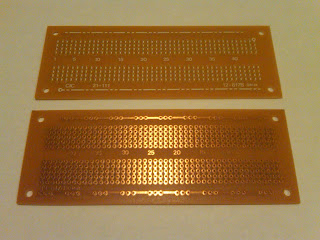
Prototyping breadboard with 45 rows of connections for dual-inline-package parts. For soldering together small circuits, these boards aren't bad. (Electronics Goldmine has these boards for $2.)


A better construction technique is deadbug on copper clad. This board is a simple oscillator that Jim Williams built in the deadbug style (a demonstration of [2]; also see [3]).


A pile of deadbug circuit boards built by Jim Williams (his lab bench really looked like this).


The good life. A custom evaluation board (this one is for the Analog Devices AD6816 networking chip with many SMA connectors).


The low-cost circuit board from a floppy disk drive (a single-sided PCB, that includes a "square-wave" trace around the motor for the position encoder).


Left: The one-transistor keypad from an original AT&T touch-tone phone (see [4]). Right: the circuit board for a more recent phone.


A ruggedized power supply (you can tell it's "rugged" from all the epoxy holding the parts in place).


The controller board from an inkjet printer, which includes a wide variety of IC packages such as the socketed DIP, several SOICs, and that EPSON ASIC in the middle with a million pins on tiny spacing.


The PCB inside a Spectral Synthesis ADDA2218, an 18-bit analog-to-digital audio converter, which uses colored FR4 (the color isn't just painted on, it's also impregnated in the fiberglass). I thought this was a neat touch, for a circuit board that only one-in-a-thousand customers would ever see (only those willing to void their warranty!).

References

[1] Jim Williams, "High speed amplifier techniques: A designer's companion for wideband circuitry," Linear Technology Corp., Milpitas, Calif., Application Note 47, Aug. 1991.
[2] Bernard M. Oliver, "The effect of mu-circuit non-linearity on the amplitude stability of RC oscillators," Hewlett-Packard Journal, vol. 11, no. 8, pp. 1-8, Apr. 1960.
[3] Jim Williams, "Max Wien, Mr. Hewlett, and a rainy Sunday afternoon," in Analog Circuit Design: Art, Science, and Personalities, Jim Williams, Ed. Boston: Butterworth-Heinemann, 1991, ch. 7, pp. 43-55.
[4] L. Schenker, "Pushbutton calling with a two-group voice-frequency code," Bell System Technical Journal, vol. 29, no. 1, pp. 235-255, Jan. 1960.

Tuesday, January 22, 2013

Purpose

The purpose of this blog is serve as the course website, including
  • Lists of assignments, including labs and readings
  • Recommended online resources
  • Synopses of lecture topics
  • Discussion forums for students (in the comments)
Also, this blog will provide an online record of our work this term, such as
  • Gear teardowns/autopsies with pictures, diagrams, lists, and text
  • Reversed-engineered documentation packages from commercial electronics
  • Design project documentation and demonstrations
  • Guides and suggestions for future students

Monday, January 21, 2013

Course description

Through a series of projects, we will learn to design, build, and debug electronic prototype systems. We will cover multiple aspects of the prototyping process, including circuit and system design, soldering, deadbugging, troubleshooting, component selection, schematic capture, printed-circuit board (PCB) layout, PCB fabrication, PCB assembly, and thermal analysis. We will discuss the tradeoffs among "faster, better, cheaper", and explore examples in the realms of analog, digital, RF, and power. In addition to hands-on reverse engineering and fabrication experience, students will learn technical communication through design documentation.